Section outline

    • Heterogeneous systems

      A heterogeneous computer system is a system that, in addition to the classic central processing unit (CPU) and memory, also contains one or more different accelerators. Accelerators are computing units that have their own process elements and their own memory, and are connected to the central processing unit and main memory via a fast bus. A computer that contains accelerators in addition to the CPU and main memory is called a host. The figure below shows an example of a general heterogeneous system.


      Today we know a series of accelerators. The most widely used are graphics processing units (GPUs) and programmable field arrays (FPGAs). Accelerators have a large number of dedicated process units and their own dedicated memory. Their process units are usually adapted to specific problems (for example, performing a large number of matrix multiplications) and can perform these problems fairly quickly (certainly much faster than a CPU). We call an accelerator a device.

      Devices process data in their memory (and their address space) and in principle do not have direct access to the main memory on the host. On the other hand, the host can access the memories on the accelerators, but cannot address them directly. It accesses the memories only through special interfaces that transfer data via the bus between the device memory and the main memory of the host.

      The figure below shows the organization of a smaller heterogeneous system such as that found in a personal computer. The host is a personal desktop computer with an Intel i7 processor.

      The main memory of the host is in DDR4 DIMMs and is connected to the CPU via a memory controller and a two-channel bus. The CPU can address this memory (for example, with LOAD / STORE commands) and store commands and data in it. The maximum theoretical single channel transfer rate between the DIMM and the CPU is 25.6 GB / s. The accelerator in this heterogeneous system is the Nvidia K40 graphics processing unit. It has a large number of process units (we will get to know them below) and its own memory (in this case it has 12 GB of GDDR5 memory). Memory in the GPE can be addressed by process units in the GPE, but cannot be addressed by the CPU on the host. Also, processors on the GPE cannot address the main memory on the host. The GPE (device) is connected to the CPU (host) via a high-speed 16-channel PCIe 3.0 bus, which enables data transfer at a maximum of 32 GB / s. Data between the main memory on the host and the GPE memory can only be transferred by the CPU via special interfaces.

      Programming of heterogeneous systems

      We will use the OpenCL framework to program heterogeneous computer systems. Programs written in the OpenCL framework consist of two parts:
      • program to be run on the host and
      • program running on the device (accelerator).

      A host program


      The program on the host will be written in the C programming language as part of the workshop. It is an ordinary program contained in the C function main(). The task of the program on the host is to:
      • determine what devices are in the system,
      • prepare the necessary data structures for the selected device,
      • create buffers to transfer data to and from the device
      • reads and translates from a file the program that will run on the device,
      • the translated program downloads along with the data to the device and runs it,
      • after the program runs on the device, it transfers the data back to the host.
      Program on the device

      We will write programs for devices in the OpenCL C language. We will learn that this is actually a C language with some changed functionalities. Programs written for the device are first translated on the host, then the host, along with the data and arguments, transfers them to the device where they are executed. The program running on the device is called a kernel. Pliers are run in parallel - a large number of process units on the device are run by the same kernel. In the following, we will get to know the implementation model provided for the devices by the OpenCL framework. The OpenCL framework provides the same runtime model and the same memory hierarchy for all types of devices, so we can program very different devices with it. In the workshop, we will limit ourselves to programming graphic process units.
    • Anatomy of graphic process units

      To make it easier to understand the operation and structure of modern graphic units, we will look below at a simplified description of the idea that led to their emergence. GPUs were created in the desire to execute program code which has a large number of relatively simple and repetitive operations on a large number of smaller processing units and not on a large, complex and energy-hungry central processing unit. Many of the problems that modern GPUs are designed for include: image and video processing, operations on large vectors and matrices, deep learning, etc.

      Modern CPUs are very complex digital circuits that speculatively execute commands in multiple pipelines, and the commands support a large number of diverse operations (more or less complex). CPUs have built-in branch prediction units and trace types in the pipelines, in which they store microcodes of commands waiting to be executed. Modern CPUs have multiple cores and each core has at least a first-tier L1 cache. Due to the above, the cores of modern CPUs together with caches occupy a lot of space on the chip and consume a lot of energy. In parallel computing, we strive to have as many simple process units as possible that are small and energy efficient. These smaller processing units typically operate at a clock speed several times lower than the CPU clock clock. Therefore, smaller process units require a lower supply voltage and thus significantly reduce energy consumption.


      The figure above shows how power and power consumption can be reduced in a parallel system. On the left side of the image is a CPU that processes with frequency f. To work with frequency f, it needs the energy it gets from the supply voltage V. The internal capacitance (that is, a kind of inertia that resists rapid voltage changes on digital connectors) of such a CPU depends mainly on its size on the chip and is marked with C. The power required by the CPU for its operation is proportional to the clock frequency, the square of the supply voltage and the capacitance.

      On the right side of the image, the same problem is solved with two CPU' processing units connected in parallel. Suppose that our problem can be broken down into two exactly the same subproblems, which we can solve separately, each on its own CPU'. Assume also that the CPUs' processing units are half the size of the CPU in terms of chip size and that they operate at a frequency of f/2. Because they work at half frequency, they also need less energy. It turns out that if we halve the clock frequency in a digital system, we only need 60% of the supply voltage for the system to work. As the CPUs are half as small, their capacitance is only C/2. The power P' that such a parallel system now needs for its operation is only 0.36 P.

      The evolution of GPU

      Suppose that we want to add two vectors vecA and vecB with the function vectorAdd() in C and save the result in the vector vecC. All vectors are of length 128.

      In the code above, we intentionally used the while loop, in which we sum all the output elements of the vectors. The index of the current element was intentionally written with a tid, which is an abbreviation of thread index. Why we chose just such a name, we find out below.

      Execution on one CPU

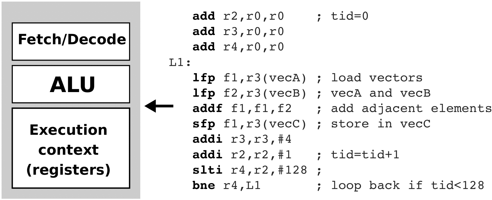
      Let's suppoes we want to run the vectorAdd() function on one simple CPU, which is shown in the figure below. The CPU has logic for capturing and decoding commands, an arithmetic-logic unit, and a set of registers containing operands for the arithmetic-logic unit.


      In addition to the CPU, the pseudo-collection code of the vectorAdd() function is shown in the figure above. We won’t go into its details, let’s just point out that the code in loop L1 is repeated 128 times.

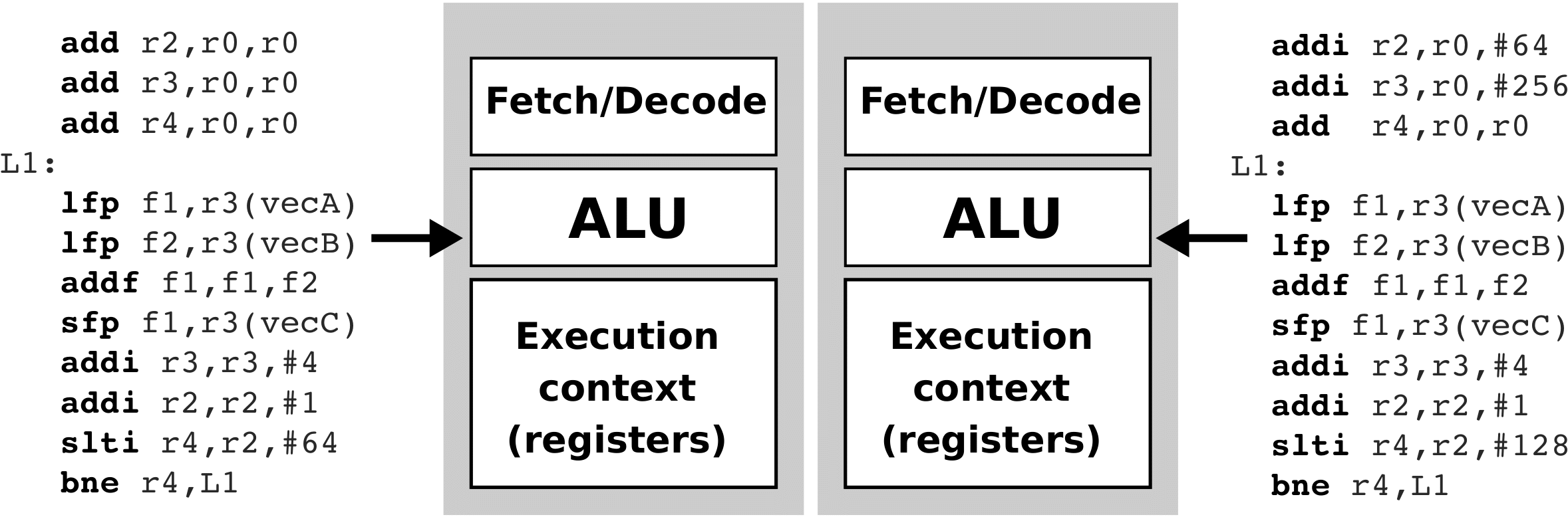
      Execution on two CPUs

      Now let's suppose we want to run the vectorAdd() function on two identical CPUs as before. The figure below shows the two CPUs and the pseudo-compiler codes running on each of these two CPUs. Again, we won’t go into the details of the collection code. Note only that the code in the L1 loop is repeated only 64 times this time, as each CPU this time adds only half of the identical elements in the vectors (the left CPU adds the first 64 elements, while the right CPU adds the last 64 elements). We can estimate that the implementation of the vectorAdd() function has been accelerated twice. We also say that two parallel threads are now running on two CPUs at the same time.

      Compute unit and process elements


      Let's suppose now that the upper CPU is expanded so that instead of a single arithmetic-logic unit it has eight arithmetic logic units. In addition, we add eight register strings to it, so that each arithmetic-logic unit can have its own set of registers in which to store its operands. In this way, arithmetic-logic units can calculate simultaneously, independently of each other! So, instead of replicating the entire CPU eight times, this time we only replicated its arithmetic-logic units and register string eight times. Such a CPU is shown in the figure below.

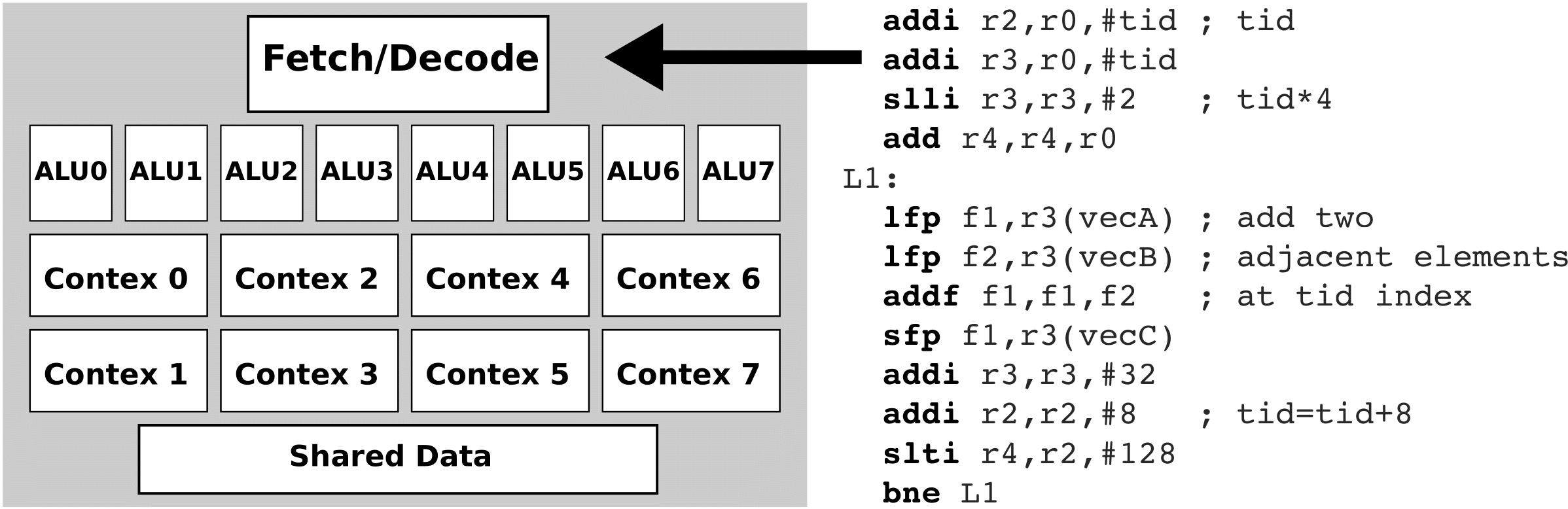
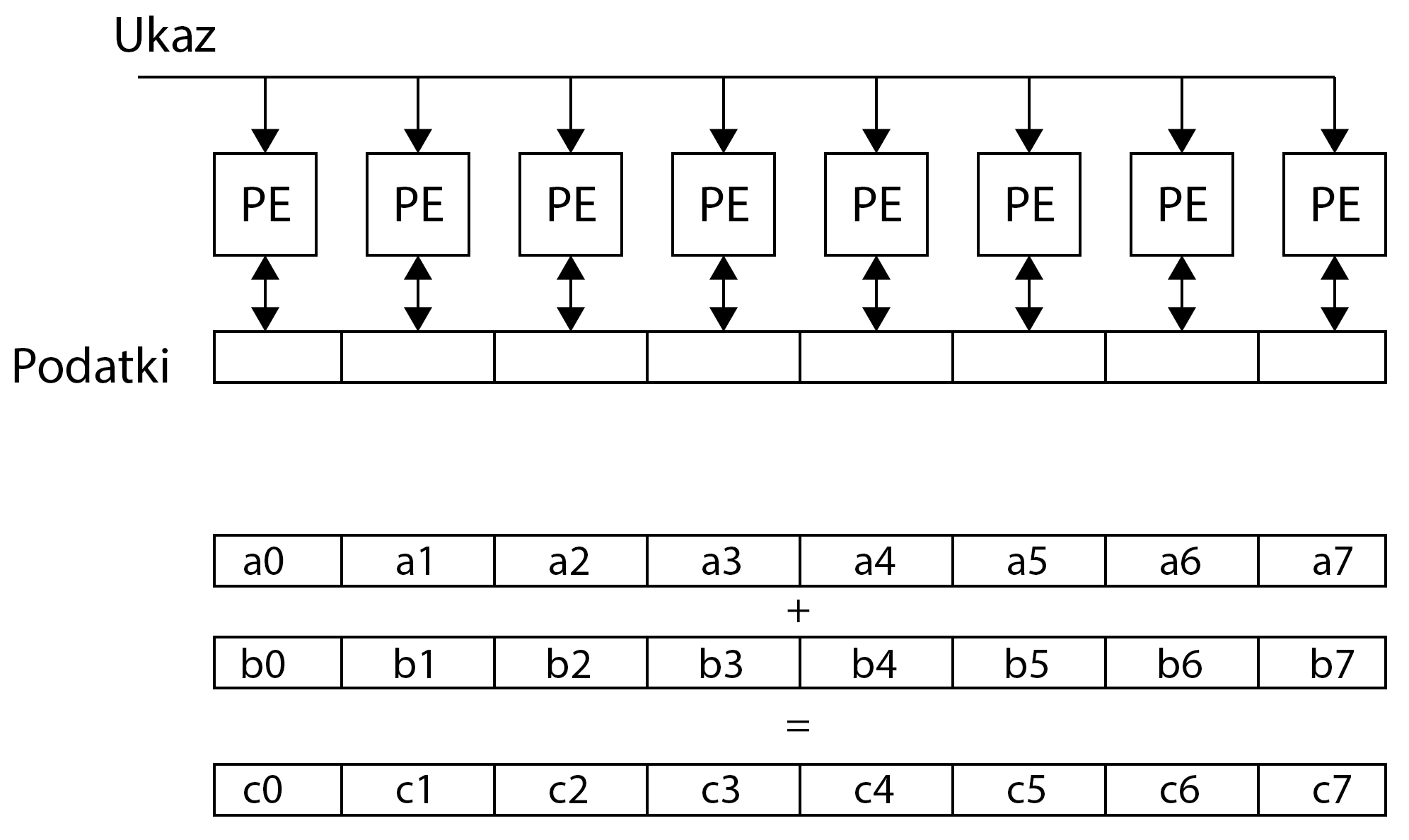
      Note, however, that such a CPU still has only one unit for capturing and decoding commands - this means that it can only take over and decode one command in one clock cycle! Therefore, such a CPU will issue the same execution command to all arithmetic-logic units. However, this time the operands in the command can be vectors of length 8. This means that we will now be able to add 8 identical elements in the vector in one cycle (simultaneously) and repeat the loop only 16 times. Such a processing unit will be called a compute unit (CU). A compute unit can execute a single command over a large amount of data - in fact, in our case, a compute unit will add eight identical vector elements with just one command to read and decode. This method of implementation is called SIMD (Single Instruction Multiple Data). Because the compute unit executes each command in eight arithmetic-logic units, it looks as if different threads of the same command string are executed in arithmetic-logic units over different data. Therefore, such an implementation is also called SIMT (Single Instruction Multiple Threads). Arithmetic-logic units that execute the same command over different operands are called processing elements (PE). The figure below shows the SIMD (SIMT) execution of commands.

      The registers in the process elements are usually private for each process element separately, which means that other process elements cannot access the data in the registers. through which they can even share data. The L1 loop is repeated only 16 times this time!

      Graphic processing unit


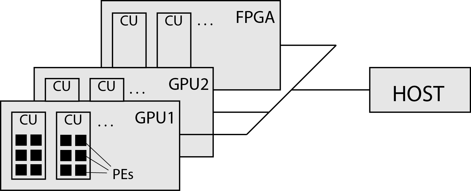
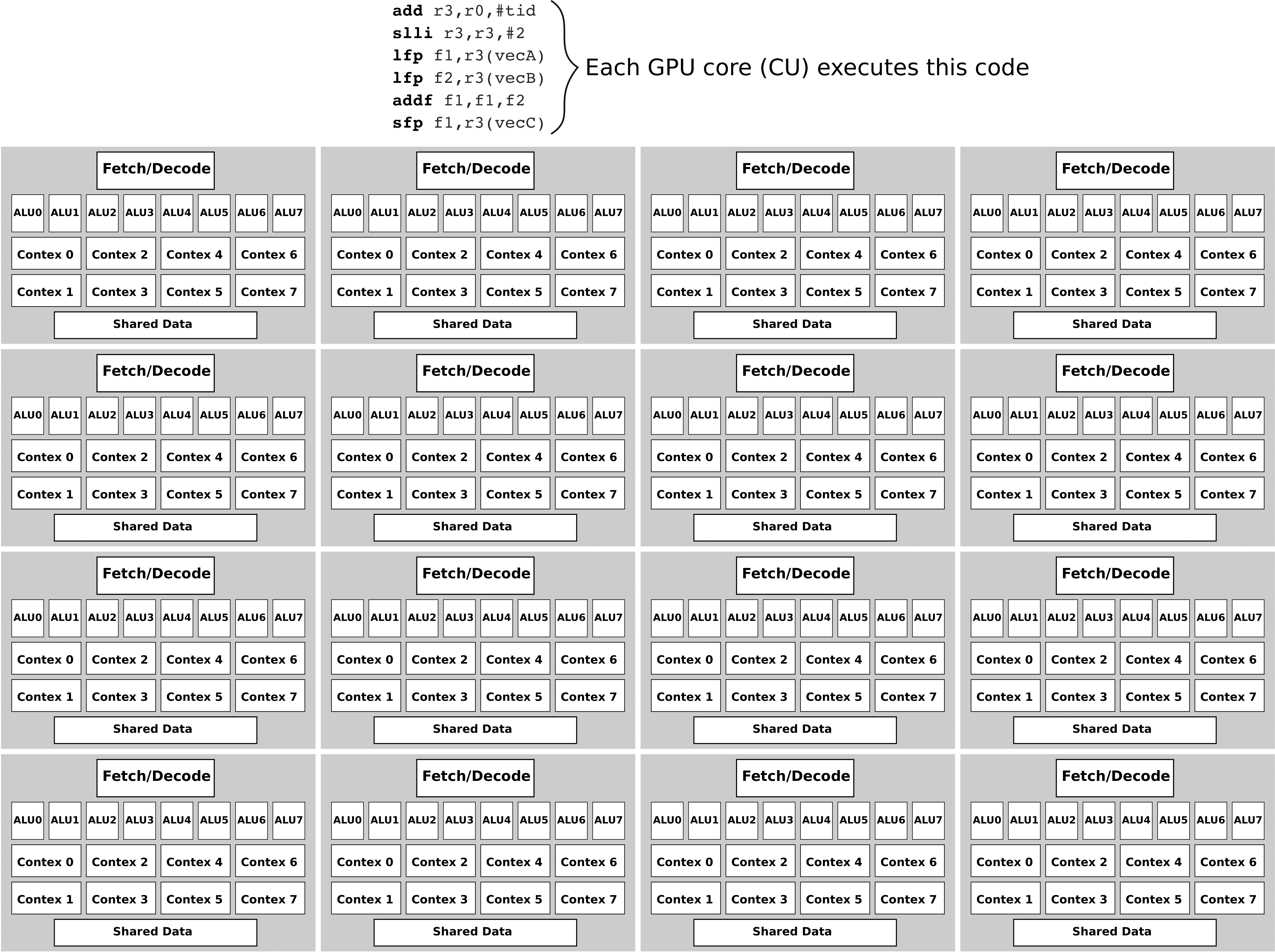
      Let's take it one step further. Instead of one calculation unit in the system, we use as many as 16 calculation units, as shown in the figure below.

      Now we do not have to repeat the loop 16 times but assign only one iteration of the loop to each compute unit. The figure above shows a simplified structure of graphic processing units.

      Summary


      Graphic processing units consist of a large number of mutually independent compute units. Compute units consist of a large number of processing elements. In a slightly simplified way, we can assume that all compute units, hereinafter referred to as CUs, execute the same program (kernel), and the process elements (PE) within one CU execute the same commands at the same time. In doing so, different CUs may perform different parts of the tongs at some point. We also say that compute units execute groups of threads, and process elements execute individual threads.